A Deep Dive into Legacy Bootkits and Rootkits
This blog post are the notes of the essential concepts of the legacy BIOS bootup process and the different infections methods used by the malware at that time. This blog post mainly relies in the information extracted from the chapters 5 to 7 of the book “Rootkits and Bootkits: Reversing Modern Malware and Next Generation Threats” by Alex Matrosov, Eugene Rodionov, and Sergey Bratus. All the figures and tables used in this blog post are original from the book. This book offers a deep dive into the legacy and actual boot process, the secure mesure imposed until 2019, the infection techniques used by bootkits and rootkits and how to analyize those kinds of threads. I consider the book a great and understandable resource about this topic, so you may want to check it out.
Without further ado, lets begin.
The Windows Boot Process
The boot process is the series of steps a computer system follows to initialize hardware and load the operating system (OS). This process can be broken down into several stages, each critical for preparing the system for use.
BIOS andd Preboot environment
When you power on a computer, the first step is the Power-On Self-Test (POST). During POST, the system performs diagnostics on the hardware components, ensuring everything is functioning correctly. This includes checking the memory, processor, and other essential peripherals. If any hardware issues are detected, POST will alert the user through error messages or beeps, halting the boot process.
Once POST is complete, the system’s BIOS (Basic Input/Output System) takes over. The BIOS is firmware stored on a chip on the motherboard, responsible for initializing hardware components and preparing the system to load the operating system. This simplified I/O interface first becomes available in the preboot environment, and is later replaced by different operating system abstractions. The most interesting of these services in terms of bootkit analysis is the disk service, accessible through a special handler known as the interrupt 13h handler, or simply INT 13h. More on this later.
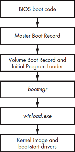
After the BIOS has initialized the hardware, it proceeds to search for a bootable device. This device can be a hard drive, SSD, or a removable drive such as a USB stick or CD/DVD. The BIOS uses a predefined boot order to determine which device to check first. This is achieved by the Master Boot Record.
The Master Boot Record (MBR)
The MBR is a data structure containing information on hard drive partition and the boot code Its primary function is to identify the active partition containing the operating system’s boot sector. Once the active partition is determined, the MBR reads and executes its boot code to start the loading process of the OS.
The MBR structure looks like the following:
1
2
3
4
5
typedef struct _MASTER_BOOT_RECORD{
	BYTE bootCode[0x1BE]; // space to hold actual boot code
	MBR_PARTITION_TABLE_ENTRY partitionTable[4];
	USHORT mbrSignature; // set to 0xAA55 to indicate PC MBR format
} MASTER_BOOT_RECORD, *PMASTER_BOOT_RECORD;
- BootCode (446 bytes): This small piece of code is responsible for loading the Volume Boot Record (VBR) in the first sector of the active partition and transfers control to it.
- Partition Table (64 bytes): Following the bootloader, contains entries for up to four primary partitions on the disk. Each entry includes details like the partition type, starting and ending sectors, and whether the partition is active (bootable).
- Boot Signature (2 bytes): A magic number (0x55AA) that indicates the end of the MBR. This signature is essential for the BIOS to recognize the MBR as valid.
The BootCode
The boot code is the small piece of code stored within the MBR. This initial bootloader code, sometimes referred to as the “first-stage bootloader,” has the critical task of loading a more complex bootloader or boot manager, often located in a specific partition. The first-stage bootloader’s primary responsibility is to locate and load the “second-stage bootloader” into memory. This second-stage bootloader is responsible for loading the operating system kernel.
For example, in a typical Linux system using GRUB (GRand Unified Bootloader), the first-stage bootloader in the MBR loads the GRUB second-stage bootloader from a designated partition. GRUB then presents a menu to the user, allowing them to select from multiple operating systems or kernels. In the case of Windows OS, the second-stage bootloader is called the bootmgr which, in essence, does the same task as GRUB.
The MBR Partition Table
The partition table is a data structure that provides information about the partitions on the disk. It includes details such as the size, location, and type of each partition.
1
2
3
4
5
6
7
8
typedef struct _MBR_PARTITION_TABLE_ENTRY {
	BYTE status; // active? 0=no, 128=yes
	BYTE chsFirst[3]; // starting sector number
	BYTE type; // OS type indicator code
	BYTE chsLast[3]; // ending sector number
	DWORD lbaStart; // first sector relative to start of disk
	DWORD size; // number of sectors in partition
} MBR_PARTITION_TABLE_ENTRY, *PMBR_PARTITION_TABLE_ENTRY;
Typically, a disk can have up to four primary partitions, one of which can be an extended partition that contains additional logical partitions. The partition table helps the system understand how the storage space on the disk is divided and where each partition begins and ends.
Look at this example:
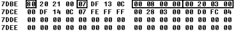
The image shows two entries (the top two lines) indicating there are only two partitions on the disk. The first partition entry starts at the address 0x7DBE. Its first byte shows this partition is active (0x80), so the MBR boot code loads and executes its Volume Boot Record (VBR), which is the first sector of that partition. The byte at offset 0x7DC2 indicates the partition type, such as the filesystem type expected by the OS, bootloader, or other low-level disk access code. In this case the value is 0x07, which corresponds to Microsoft’s NTFS.
The DWORD at 0x7DC5 in the partition table entry shows the partition starts at offset 0x800 from the beginning of the hard drive, measured in sectors. The last DWORD specifies the partition’s size in sectors (0x32000). This table summaries the values in the MBR partition table of the image.
| Partition index | Is active | Type | Beginning offset, sectors (bytes) | Partition size, sectors (bytes) |
|---|---|---|---|---|
| 0 | True | NTFS (0x07) | 0x800 (0x100000) | 0x32000 (0x6400000) |
| 1 | False | NTFS (0x07) | 0x32800 (0x6500000) | 0x4FCD000 (0x9F9A00000) |
| 2 | N/A | N/A | N/A | N/A |
| 3 | N/A | N/A | N/A | N/A |
The Volume Boot Record (VBR) and Initial Program Loader (IPL)
The Volume Boot Record, also known as the partition boot sector, resides in the first sector of a partition on a storage device. Unlike the Master Boot Record (MBR), which contains information about the disk as a whole and its partition table, the VBR is specific to each partition.
The Volume Boot Record (VBR) holds essential information about the partition, including the filesystem type and its parameters, as well as executable code responsible for loading the Initial Program Loader (IPL) from the active partition. The IPL, in turn, contains the necessary logic to parse the filesystem, enabling it to read files from the partition.
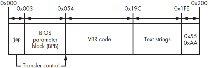
The VBR Structure
The VBR typically contains the following elements:
- Boot Code: The code responsible for loading the IPL
- BIOS Parameter Block (BPB): A data structure that stores information about the file system on the partition, such as the sector size, cluster size, and the number of sectors per track. This information is crucial for the boot code to correctly interpret and access the file system on the partition.
- Text Strings: Used to display them to a user if an error occurs.
- Signature: A 2-byte signature of the VBR, 0xAA55.
1
2
3
4
5
6
7
8
9
10
11
12
13
14
15
16
17
18
19
20
21
22
23
24
25
26
27
28
29
30
31
32
33
34
35
typedef struct _BIOS_PARAMETER_BLOCK_NTFS {
WORD SectorSize;
BYTE SectorsPerCluster;
WORD ReservedSectors;
BYTE Reserved[5];
BYTE MediaId;
BYTE Reserved2[2];
WORD SectorsPerTrack;
WORD NumberOfHeads;
DWORD HiddenSectors;
BYTE Reserved3[8];
QWORD NumberOfSectors;
QWORD MFTStartingCluster;
QWORD MFTMirrorStartingCluster;
BYTE ClusterPerFileRecord;
BYTE Reserved4[3];
BYTE ClusterPerIndexBuffer;
BYTE Reserved5[3];
QWORD NTFSSerial;
BYTE Reserved6[4];
} BIOS_PARAMETER_BLOCK_NTFS, *PBIOS_PARAMETER_BLOCK_NTFS;
typedef struct _BOOTSTRAP_CODE{
BYTE bootCode[420]; // boot sector machine code
WORD bootSectorSignature; // 0x55AA
} BOOTSTRAP_CODE, *PBOOTSTRAP_CODE;
typedef struct _VOLUME_BOOT_RECORD{
WORD jmp;
BYTE nop;
DWORD OEM_Name
DWORD OEM_ID; // NTFS
BIOS_PARAMETER_BLOCK_NTFS BPB;
BOOTSTRAP_CODE BootStrap;
} VOLUME_BOOT_RECORD, *PVOLUME_BOOT_RECORD;
When the BIOS or UEFI identifies a bootable partition, it reads and executes the VBR’s boot code. This boot code is responsible for locating the Initial Program Loader (IPL), which location is specified by the HiddenSectors field in the BPB structure. This field contains the offset (in sectors) from the beginning of the hard drive. The VBR’s boot code loads the IPL into memory and transfers control to it, marking the next phase of the boot process.
The Initial Program Loader (IPL)
The IPL’s primary functions include loading the complete bootloader, locating and loading the operating system kernel, and managing boot configurations. It also enables the system to boot various operating systems or kernel versions, allowing users to select their desired boot option.
The Initial Program Loader (IPL) typically occupies 15 consecutive sectors of 512 bytes each and is situated immediately after the Volume Boot Record (VBR). It contains just enough code to parse the partition’s filesystem and proceed with loading the boot manager module. The VBR and IPL work in tandem because the VBR, limited to a single sector, lacks the necessary space to include comprehensive filesystem parsing functionality on its own.
The bootmgr Module and Boot Configuration Data (BCD)
The Initial Program Loader (IPL) reads and loads the operating system’s boot manager, for Windows the bootmgr module, from the filesystem. Once the IPL hands over control to bootmgr, it takes charge of the boot process. Bootmgr reads the Boot Configuration Data (BCD), which includes critical system parameters that influence security policies, such as the Kernel-Mode Code Signing Policy.
Bootmgr continues managing the boot process until the user selects a boot option. After the user makes a choice, bootmgr launches winload.exe (or winresume.exe), which loads the operating system kernel, boot-start drivers, and some system registry data.
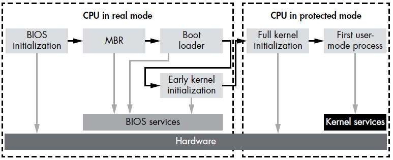
Aside: Real Mode vs Protected Mode
When a computer is first powered on, the CPU starts in real mode, an outdated execution mode that uses a 16-bit memory model. In this mode, each byte in RAM is addressed by a pointer made up of two 2-byte words: segment_start and segment_offset. This segment memory model divides the address space into segments, where the address of each byte is determined by the segment’s address and the offset of the byte within that segment. Specifically, segment_start identifies the target segment, while segment_offset specifies the byte’s position within that segment.
Real mode addressing limits the accessible system RAM to about 1 MB, as the highest address possible is FFFF, which equates to 1,114,095 bytes. This limitation is insufficient for modern operating systems and applications. To overcome this, once bootmgr takes over the boot process, it switches the processor from real mode to protected mode (or long mode on 64-bit systems). The bootmgr consists of 16-bit real-mode code and a compressed PE image. The real-mode code uncompresses the PE image, switches the CPU to protected mode, and transfers control to the uncompressed module.
Bootkits need to handle this mode switch effectively to maintain control over the boot process. After the switch, the memory layout changes significantly, and code that was previously in a contiguous memory block may be relocated to different segments. Bootkits must incorporate sophisticated techniques to navigate these changes and retain control of the boot sequence.
BCD Boot Variables
The BCD store holds all the information bootmgr needs to load the OS. This includes the partition path for the OS, available boot applications, code integrity settings, and parameters for booting in modes like preinstallation or safe mode. Some BCD boot variables are pretty important while analyzing bootkits due to the direct impact they have over some security checks:
| Variable name | Description | Type | Parameter ID |
|---|---|---|---|
| BcdLibraryBoolean_DisableIntegrityCheck | Disables kernel-mode code integrity checks | Boolean | 0x16000048 |
| BcdOSLoaderBoolean_WinPEMode | Tells the kernel to load in preinstallation mode, disabling kernel-mode code integrity checks as a byproduct | Boolean | 0x26000022 |
| BcdLibraryBoolean_AllowPrereleaseSignatures | Enables test signing (TESTSIGNING) | Boolean | 0x1600004 |
The BcdLibraryBoolean_DisableIntegrityCheck variable disables integrity checks, allowing unsigned kernel-mode drivers to load. However, this option is ignored in Windows 7 and cannot be set if Secure Boot is enabled.
The BcdOSLoaderBoolean_WinPEMode variable directs the system to start in Windows Preinstallation Environment Mode, a minimal OS used for preparing systems for Windows installation. This mode also bypasses kernel integrity checks, including the mandatory Kernel-Mode Code Signing Policy for 64-bit systems.
The BcdLibraryBoolean_AllowPrereleaseSignatures variable permits loading of kernel-mode drivers signed with test certificates. These certificates can be generated with tools from the Windows Driver Kit. For example, the Necurs rootkit uses this method to install a malicious driver signed with a custom certificate.
After retrieving boot options, bootmgr performs a self-integrity check. If this check fails, bootmgr halts the boot process and displays an error. However, if any of those more is set to TRUE, this self-check is skipped, making bootmgr susceptible to tampering.
Windows Early Kernel Initialization
Once BCD parameters are loaded and self-integrity is verified, bootmgr selects the appropriate boot application. For a fresh OS load from the hard drive, it uses winload.exe; for resuming from hibernation, it uses winresume.exe.
When winload.exe takes over, it enables paging in protected mode and loads the OS kernel image along with dependencies, including:
bootvid.dll: VGA support library for boot timeci.dll: Code integrity libraryclfs.dll: Common logging filesystem driverhal.dll: Hardware abstraction layer librarykdcom.dll: Kernel debugger protocol communications librarypshed.dll: Platform-specific hardware error driver
Additionally, winload.exe loads boot-start drivers, including storage device drivers, Early Launch Anti-Malware (ELAM) modules, and the system registry hive.
Note
In order to read all the components from the hard drive, winload.exe uses the interface provided by bootmgr. This interface relies on the BIOS INT 13h disk service. Therefore, if the INT 13h handler is hooked by a bootkit, the malware can spoof all data read by winload.exe.
winload.exe verifies the integrity of executables according to the system’s code integrity policy. Once all modules are successfully loaded, control is transferred to the OS kernel image for further initialization, as detailed in subsequent chapters.
Boot Process Security
In this section, we’ll explore two key security mechanisms in the Microsoft Windows kernel: the Early Launch Anti-Malware (ELAM) module, and the Kernel-Mode Code Signing Policy. Both mechanisms aim to block unauthorized code from running in the kernel address space, enhancing protection against rootkits. We’ll examine how these mechanisms work, their strengths and weaknesses, and evaluate their effectiveness in combating rootkits and bootkits.
The Early Launch Anti-Malware Module
Introduced in Windows 8, the Early Launch Anti-Malware (ELAM) module allows third-party security software to register a kernel-mode driver that is guaranteed to execute early in the boot process, before any other third-party drivers. This early execution ensures that security software can inspect and prevent the loading of malicious drivers, very common behavior in rootkits.
API Callback Routines
ELAM operates by registering callback routines that the kernel uses to evaluate data in the system registry hive and boot-start drivers. These callbacks are critical for detecting and preventing the loading of malicious modules. The key API routines involved are:
- CmRegisterCallbackEx and CmUnRegisterCallback: Used to register and unregister callbacks for monitoring registry data.
- IoRegisterBootDriverCallback and IoUnRegisterBootDriverCallback: Used to register and unregister callbacks for boot-start drivers.
Classification of Boot-Start Drivers
Boot-start drivers are categorized based on their behavior and impact on the system’s security and stability. ELAM classifies these drivers to facilitate better decision-making regarding their loading during the boot process. The classifications include:
- Good: Drivers known to be legitimate and clean
- Bad: Known to be malicious
- Unknown: Drivers that ELAM can’t classify
Unfortunately, the ELAM driver must base this decision on limited data about the driver image to classify, namely:
- The name of the image
- The registry location where the image is registered as a boot-start driver
- The publisher and issuer of the image’s certificate
- A hash of the image and the name of the hashing algorithm
- A certificate thumbprint and the name of the thumbprint algorithm
Note
The ELAM driver doesn’t receive the image’s base address, nor can it access the binary image on the hard drive because the storage device driver stack isn’t yet initialized (as the system hasn’t finished bootup). It must decide which drivers to load based solely on the hash of the image and its certificate, without being able to observe the image itself. As a consequence, the protection for the drivers is not very effective at this stage.
ELAM Policy
Windows determines whether to load known bad or unknown drivers based on the ELAM policy specified in the registry key: HKLM\System\CurrentControlSet\Control\EarlyLaunch\DriverLoadPolicy.
| Policy name | Policy value | Description |
|---|---|---|
| PNP_INITIALIZE_DRIVERS_DEFAULT | 0x00 | Load known good drivers only |
| PNP_INITIALIZE_UNKNOWN_DRIVERS | 0x01 | Load known good and unknown drivers only |
| PNP_INITIALIZE_BAD_CRITICAL_DRIVERS | 0x03 | Load known good, unknown, and known bad critical drivers (This is the default setting) |
| PNP_INITIALIZE_BAD_DRIVERS | 0x07 | Load all drivers |
By default, the ELAM policy PNP_INITIALIZE_BAD_CRITICAL_DRIVERS allows the loading of bad critical drivers. This means that if a critical driver is classified by ELAM as known bad, the system will still load it. The reasoning behind this policy is that critical system drivers are essential for the operating system’s functionality; if any critical driver fails to initialize, the operating system will be unable to boot. Thus, this ELAM policy prioritizes availability and serviceability over security to ensure the system can start.
However, this policy does not load known bad noncritical drivers, meaning drivers that are not essential for the operating system to boot successfully.
Bypassing ELAM
ELAM provides security software with an advantage against rootkit threats, but it is not effective against bootkits-and it wasn’t designed to be. ELAM can only monitor legitimately loaded drivers, while most bootkits load kernel-mode drivers using undocumented operating system features. This allows bootkits to bypass security enforcement and inject their code into the kernel address space despite ELAM’s presence. Moreover, a bootkit’s malicious code runs before the operating system kernel is initialized and before any kernel-mode driver, including ELAM, is loaded. This allows bootkits to evade ELAM protection entirely:
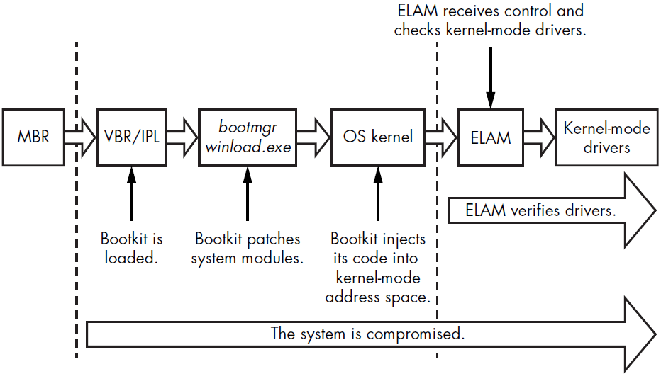 Most bootkits load their kernel-mode code during the middle of kernel initialization, after all OS subsystems (such as the I/O subsystem, object manager, plug and play manager, etc.) have been initialized, but before ELAM is executed. Since ELAM cannot prevent the execution of malicious code that is loaded prior to its activation, it has no defenses against bootkit techniques.
Microsoft Kernel-Mode Code Signing Policy
The Kernel-Mode Code Signing Policy was introduced in Windows Vista and aims to protect the Windows operating system by enforcing code-signing requirements for kernel-mode modules at time of loading. This policy makes it significantly more difficult for unauthorized code to execute within the kernel space.
This feature is enforced differently on 32-bit and 64-bit operating systems as this table shows:
| Driver type | Integrity check? 64-bit | Integrity check? 32-bit |
|---|---|---|
| Boot-start drivers | Yes | Yes |
| Non-boot-start PnP drivers | Yes | No |
| Non-boot-start, non-PnP drivers | Yes | No (except drivers that stream protected media) |
Drivers must have an embedded Software Publisher Certificate (SPC) digital signature or a catalog file with an SPC signature. Boot-start drivers can only have embedded signatures due to the unavailability of the storage device driver stack during early boot.
The Legacy Code Integrity Weakness
The logic enforcing the Kernel-Mode Code Signing Policy is divided between the Windows kernel image and the kernel-mode library ci.dll. The kernel uses this library to verify the integrity of all modules loaded into the kernel address space. The system lies in a single point of failure within this code.
This weakness have been spotted with the Uroburos malware family, which by setting nt!g_CiEnabled variable to FALSE, allowed unsigned drivers to be loaded. This weakness exposes the system to potential threats even with integrity checks ostensibly in place.
Secure Boot Technology
Secure Boot, introduced in Windows 8, leverages the Unified Extensible Firmware Interface (UEFI) to ensure that only code with a valid digital signature can be executed during the boot process. This mechanism is designed to protect the integrity of the operating system kernel, system files, and boot-critical drivers.
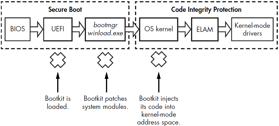 When Secure Boot is enabled, the BIOS checks the integrity of all UEFI and OS boot files executed at startup to ensure they originate from a legitimate source and have a valid digital signature. The
 winload.exe and the ELAM driver verify the signatures of all boot-critical drivers as part of Secure Boot’s validation. While similar to the Microsoft Kernel-Mode Code Signing Policy, Secure Boot specifically applies to modules executed before the OS kernel is loaded and initialized. As a result, untrusted components without valid signatures are not loaded and trigger remediation.
At system startup, Secure Boot ensures the preboot environment and bootloader components remain untampered. The bootloader then validates the integrity of the kernel and boot-start drivers. Once the kernel passes these integrity checks, Secure Boot proceeds to verify other drivers and modules.
Secure Boot operates on the principle of a root of trust, assuming the system is trustworthy early in its execution. However, if attackers manage to execute an attack before this point, they can potentially bypass these protections.
Virtualization-Based Security in Windows 10
Windows 10 introduced Virtual Secure Mode (VSM) and Device Guard, which use hardware-assisted memory isolation to enhance code integrity protections. These technologies leverage Second Level Address Translation (SLAT) to improve security and performance.
Virtual Secure Mode
Virtual Secure Mode (VSM) first appeared in Windows 10, leveraging Microsoft’s Hyper-V to provide virtualization-based security. VSM operates by executing the operating system and critical system modules in isolated, hypervisor-protected containers. This isolation ensures that even if the kernel is compromised, critical components in other virtual environments remain secure, preventing attackers from pivoting between compromised virtual containers. VSM also isolates code integrity components from the Windows kernel within these hypervisor-protected containers.
This isolation makes it impossible for attackers to use vulnerable legitimate kernel-mode drivers to disable code integrity, unless they find a vulnerability affecting the protection mechanism itself. By separating potentially vulnerable drivers and code integrity libraries into different virtual containers, VSM ensures that attackers cannot easily disable code integrity protection.
Device Guard
Device Guard enforces specific requirements and limitations on the driver development process, causing some existing drivers to malfunction when it is active. All drivers must adhere to the following rules:
- Allocate all nonpaged memory from the no-execute (NX) nonpaged pool. The driver’s PE module cannot have sections that are both writable and executable.
- Avoid direct modification of executable system memory.
- Do not use dynamic or self-modifying code in kernel mode.
- Do not load any data as executable.
Since most modern rootkits and bootkits do not meet these requirements, they cannot run with Device Guard active, even if the driver has a valid signature or bypasses code integrity protection.
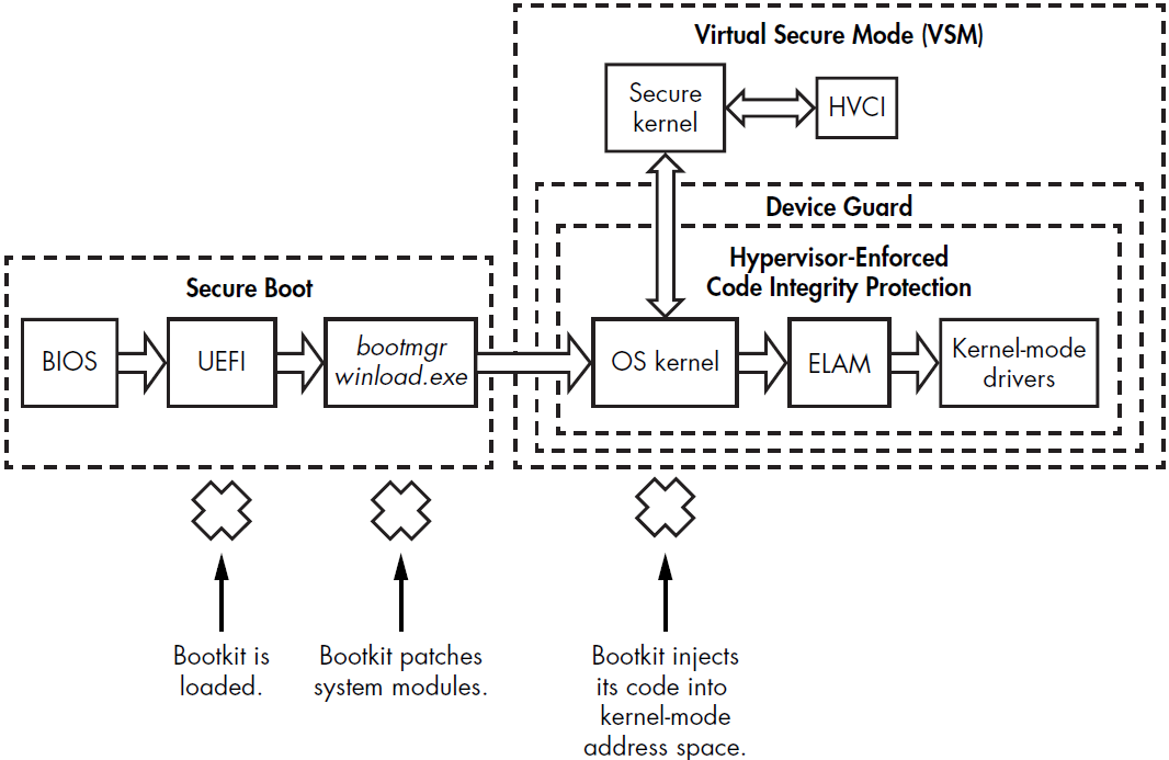
Full View
Secure Boot verifies firmware components executed in the preboot environment, including the OS bootloader, to protect against bootkits. VSM isolates the critical components responsible for enforcing code integrity (known as Hypervisor-Enforced Code Integrity (HVCI)) from the OS kernel address space.
 Secure Boot Process
- BIOS: The Basic Input/Output System initiates the boot process.
- UEFI: The Unified Extensible Firmware Interface checks the integrity of the system before handing over control to the operating system. It ensures that only firmware components with valid digital signatures are executed.
- bootmgr/winload.exe: The boot manager and Windows loader continue the boot process, verifying the integrity of OS kernel files.
- Hypervisor-Enforced Code Integrity Protection: Protects code integrity by using the hypervisor to ensure only trusted code is executed.
- Virtual Secure Mode (VSM): VSM creates isolated, hypervisor-protected containers to execute critical system components. Prevents attackers from patching critical components from a compromised kernel.
- ELAM (Early Launch Anti-Malware): Monitors and ensures that only trusted drivers are loaded early in the boot process.
Bootkit Infection Techniques
MBR Infection Techniques
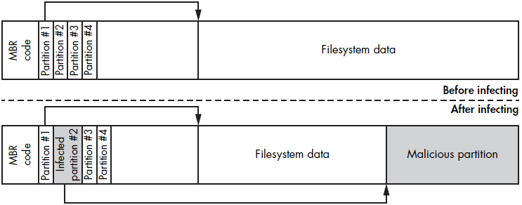
MBR-based infection methods are among the most common strategies used by bootkits to compromise the Windows boot process. These techniques typically involve modifying either the MBR code, the MBR data (such as the partition table), or both.
MBR code modification involves overwriting the system MBR code with malicious code and save the original one in some way. One common approach is to save it in a hidden location in the hard drive.
MBR data modification method involves altering the MBR partition table. This method is more challenging, because the contents of the partition table change from system to system. This also makes it more difficult for malware analysts to find a pattern that definitively indentifies the infection.
MBR Code Modification: TDL4
To illustrate this infection method we are going to analyze the TDL4 bootkit. TDL4 targets the Windows 64-bit platform, leveraging advanced evasion and anti-forensic techniques from its predecessor, TDL3. To bypass the Kernel-Mode Code Signing Policy and infect 64-bit systems, TDL4 modifies the MBR code of the bootable hard drive, replacing it with a malicious sample that is executed before the Windows kernel image. This ensures that the malicious code runs at a very early stage, enabling the malware to tamper the security mechanisms.
The infection process of TDL4 involves creating a hidden storage area at the end of the hard drive, where it writes the original MBR and its own modules. These modules include the MBR code, loaders for 16-bit, 32-bit, and 64-bit systems, the main bootkit drivers, and payloads for injecting into processes. The following table shows the different files used by the TDL$ malware:
| Module name | Description |
|---|---|
| mbr | Original contents of the infected hard drive boot sector |
| ldr16 | 16-bit real-mode loader code |
| ldr32 | Fake kdcom.dll library for x86 systems |
| ldr64 | Fake kdcom.dll library for x64 systems |
| drv32 | The main bootkit driver for x86 systems |
| drv64 | The main bootkit driver for x64 systems |
| cmd.dll | Payload to inject into 32-bit processes |
| cmd64.dll | Payload to inject into 64-bit processes |
| cfg.ini | Configuration information |
| bckfg.tmp | Encrypted list of command and control (C&C) URLs |
TDL4 infects a hard drive by sending I/O control code requests (IOCTL_SCSI_PASS_THROUGH_DIRECT) directly to the disk miniport driver. This low-level interaction bypasses standard filter kernel drivers implemented by security solutions. TDL4 uses the DeviceIoControl API to send these requests, targeting the symbolic link ??\PhysicalDriveXX, where XX is the number of the infected drive.
To open this handle with write access, administrative privileges are required. TDL4 achieves administrative permissions by exploiting the MS10-092 vulnerability in the Windows Task Scheduler service, a technique first seen in Stuxnet. The Task Scheduler runs a malicious task with administrative privileges, enabling TDL4 to infect the system successfully.
By writing data directly to the disk, TDL4 bypasses filesystem-level defenses, as the I/O Request Packet (IRP) reaches the disk-class driver directly. Once all components are installed, TDL4 forces a system reboot using the NtRaiseHardError native API, passing OptionShutdownSystem to trigger a Blue Screen of Death (BSoD). The BSoD causes an automatic system reboot, ensuring the rootkit modules load on the next boot without alerting the user. here is the boot flow just after the bootkit has been implanted:
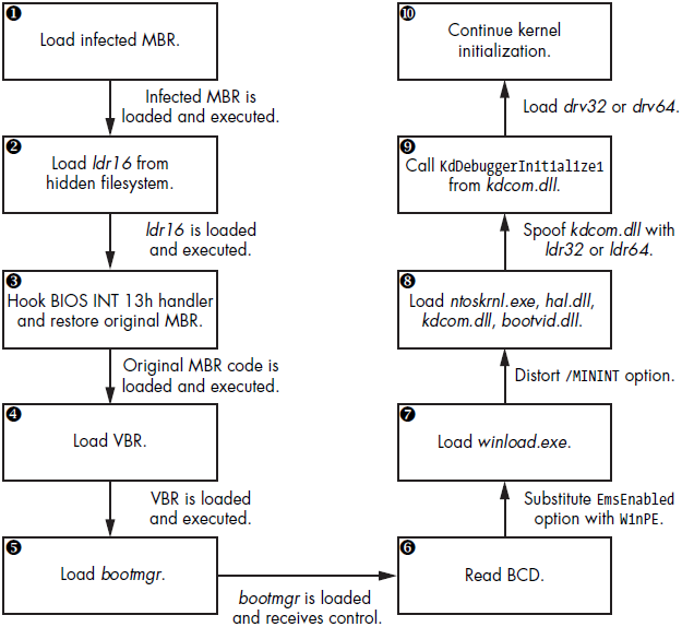
During the reboot, the BIOS reads the infected MBR into memory, executing it to load the bootkit. The infected MBR locates the bootkit’s filesystem at the hard drive’s end, loading and executing the ldr16 module. This module hooks the BIOS’s 13h interrupt handler, reloads the original MBR, and passes execution to it, allowing normal booting with a hooked interrupt handler. The original MBR is stored in the mbr module within the hidden filesystem as seen in the previous table.
The BIOS interrupt 13h service provides a crucial interface for disk I/O operations in the preboot environment, as storage device drivers are not yet loaded. Standard boot components (bootmgr, winload.exe, winresume.exe) rely on the 13h service to read system components from the hard drive.
After control transfers to the original MBR, the boot process continues, loading the VBR and bootmgr, but now the bootkit in memory controls all I/O operations. By intercepting this 13h disk services interrupt handler, the bootkit can manipulate data read from the hard drive during boot, allowing them to replace kdcom.dll with ldr32 or ldr64 from the hidden filesystem. This replacement allows the bootkit to load its driver and disable kernel-mode debugging facilities.
To replace kdcom.dll on Windows Vista and later, the malware disables kernel-mode code integrity checks temporarily. If these checks are not disabled, winload.exe would report an error and halt the boot process. The bootkit disables code integrity checks by instructing winload.exe to load the kernel in preinstallation mode, which lacks these checks. This is achieved by replacing the BcdLibraryBoolean_EmsEnabled element with BcdOSLoaderBoolean_WinPEMode in the Boot Configuration Data (BCD) when bootmgr reads the BCD from the hard drive.
Next, the bootkit turns on preinstallation mode to load the malicious kdcom.dll, then disables it as it were never enabled. The malware achieves this by manipulating the /MININT string option in winload.exe, causing the kernel to receive an invalid /MININT option and continue as if preinstallation mode weren’t enabled. The winload.exe image uses the /MININT option to notify the kernel that preinstallation mode is enabled.
The final step involves the bootkit loading a malicious kernel-mode driver (drv32 or drv64), bypassing code integrity checks.
Apart from all of that, the malicious MBR code in TDL4 is encrypted to avoid detection by static analysis. The code initializes registers with the size and offset of the encrypted code. Then, uses a loop to decrypt the code and hook the INT 13h handler, disabling OS code integrity verification and loading malicious drivers.
MBR Partition Table Modification
Another approach to MBR infection involves modifying the partition table. The Olmasco variant of TDL4 demonstrates this technique by creating a hidden partition at the end of the hard drive. This partition is marked as active so the VBR of the newly created partition is launched. This method allows the malware to infect the system without altering the MBR code, making it harder to detect. This method also allows for greater flexibility in storing and executing additional payloads, as the hidden partition can contain various components of the bootkit.
VBR/IPL Infection Techniques
While MBR infections are common, some bootkits target the Volume Boot Record (VBR) or Initial Program Loader (IPL) instead. These techniques are designed to evade security software that only checks the MBR for unauthorized modifications. The VBR and IPL are responsible for loading the operating system from the partition, making them critical points for malware infection.
IPL Modifications: Rovnix
The Rovnix bootkit exemplifies the IPL modification technique. Instead of overwriting the MBR, Rovnix modifies the IPL on the bootable hard drive’s active partition. It compresses the original IPL code, prepends its malicious bootstrap code, and writes the modified code back. Upon system startup, the malicious code hooks the INT 13h handler to patch the bootloader components and gain control once they are loaded.
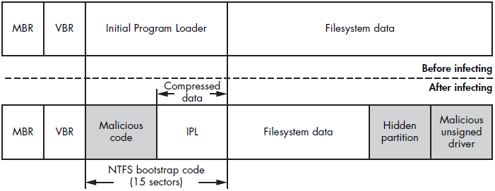
Rovnix’s infection process involves several steps to ensure its persistence and stealth. After modifying the IPL, Rovnix patches the bootloader components to load its malicious code during the boot process. It also employs various techniques to evade detection, such as using polymorphic code to change its appearance and hooking system functions to hide its activities.
By targeting the IPL, Rovnix can effectively control the boot process and ensure that its malicious payloads are executed each time the system starts.
VBR Infection: Gapz
Gapz infects the VBR by modifying only a few bytes, specifically the HiddenSectors field in the BIOS Parameter Block (BPB). This minor alteration allows the bootkit to load its malicious code instead of the legitimate IPL, effectively evading detection. The bootkit image is stored either before the first partition or after the last one on the hard drive. By targeting the VBR, Gapz can control the boot process and load its code early during system startup.
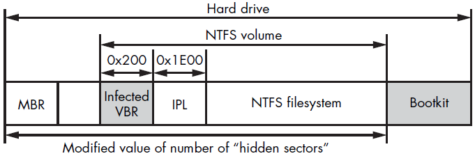
The infection process of Gapz involves altering the BPB to point to the location of its malicious code. This allows Gapz to intercept the boot process and execute its payloads before the operating system is fully loaded. Gapz also employs various evasion techniques, such as encrypting its components and using rootkit functionalities to hide its presence. By infecting the VBR, Gapz can maintain a low profile and persist on the system even if parts of it are detected and removed.